


The older version of the fieldbus coupler WAGO 750-352 is also supported.
The following WAGO 750 extension modules are recommended as they were fully tested:
750-1504, 750-1406, 750-513, 750-563
Proper work of other modules is not guaranteed. With big probability, IRT Analyzer will reject to work with modules which have mixed input-output types (digital and analog, input and output on the same module).
If a not supported module is used, IRT Analyzer may not be able to address inputs and outputs correctly even in the supported modules. Because of that program will not allow to connect to the device. A corresponding error message will be displayed. |
Before you can use WAGO 750-362 you need to configure connection parameters of the device. Enable "WAGO I/O Device" in the 'DAQ Configuration' dialog and press the 'Connect' button.
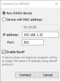
MAC address
If you have several fieldbus couplers in your network, you need to select to which of the available couplers to connect. The identification is done using the MAC address. There is a sticker with unique MAC address on every WAGO fieldbus coupler.
If you have just one fieldbus coupler, select Any WAGO device option.
IP address
WAGO fieldbus coupler supports several methods of IP address assignment. You can read about them in the WAGO fieldbus coupler documentation. In this manual you will find description of methods that we recommend to use. Please see it below.
Port
If not changed in fieldbus coupler configuration, port used to exchange data with the fieldbus coupler is 502 (default for Modbus protocol).
Enable BootP
Mark the check box to enable BootP protocol on the PC side.
Using BootP protocol to connect to a WAGO device
May not work if device's factory default configuration is changed.
We recommend using BootP protocol for IP address assignment. This is also the default method - WAGO fieldbus coupler has BootP enabled in the factory default configuration.
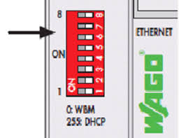
Before you try to connect to your WAGO device, please make sure that all switches on the red DIP switch on the fieldbus coupler case are set to 0. On the picture below, all switches (white) are moved to the right, OFF side.
You need to select proper IP address that will be assigned to the WAGO fieldbus coupler:
IP address of the WAGO device must belong to the same subnet with PC's network adapter to which the coupler is connected to. For example, if PC's network adapter has IP address 192.168.1.X, for the fieldbus coupler you should select IP address which also starts with 192.168.1. Make sure that no other PC or network device uses the same IP address.
To know which IP address your PC adapter has you need to find the adapter in Windows settings and check its properties.
Please also consider the following:
·If WAGO device already has an IP address assigned, it cannot be changed with BootP.
·BootP server is running only during the connection process. It is stopped as soon as appropriate WAGO device is found and connected.
·IP address negotiation with BootP protocol may take some time, but not longer than two minutes.
·If IP address assignment takes too long, you may try to restart (power-on reset) the WAGO device, then it will send a BootP request immediately after booting.
·If BootP is used as the IP address assignment method, you should leave 'Enable BootP' option on as the BootP-assigned IP address is not remembered when WAGO device is rebooted.
Using DIP switch to set IP address
Again, we assume here that factory default configuration of WAGO fieldbus coupler is not changed.
Default WAGO IP address starts with 192.168.1 and you can use the red DIP switch located on WAGO device case to set the IP address last number. There are 8 switches which allows to select a number from 0 to 255 in the binary form:
·0: WAGO WBM (web based) configuration is used, which has BootP method enabled (factory default). This is the BootP option described above.
·1-254: WAGO device will have fixed IP address 192.168.1.1-192.168.1.254, BootP protocol will not be used.
·255: WAGO device will use IP address assigned by a DHCP server (DHCP server should be available on LAN where WAGO device is connected to). This option is not recommended as DHCP assigned IP addresses are often dynamic and there is no easy way to know which address was used.
You should set 'IP address' field in 'Connect to WAGO' dialog to the same value as was configured by the DIP switch.
Other IP address selection methods
BootP and the DIP switch is not the only methods of IP address configuration. Fieldbus coupler settings can be also changed in Web-based Management System (WBM). If they are changed, methods described above may not work. Please read WAGO documentation for details.
Configuring data exchange delays for WAGO fieldbus coupler
Modbus TCP protocol is used to read input signals and to set output signal values. The protocol works in a way that PC program sends a request to the WAGO device and WAGO device reports current state of the inputs. You can configure how often to check the state of the inputs. The faster your controlled process is the higher should be the polling rate, but there are limitations.
In perfect conditions (short Ethernet cable, no interferences) it takes about 2 ms for WAGO device to respond. This allows to read input states about 500 times per second. Windows is not a real-time OS, at some moments response time may fall to about 20-40 ms. |
To open WAGO configuration dialog press 'Configure' button in the 'DAQ Configuration' dialog.
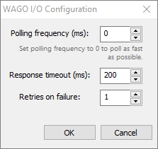
Polling frequency
Specify the delay in the polling requests in milliseconds. 10 ms delay corresponds to 100 requests per second. If you set the delay to 0, polling will be done at the maximum frequency. This frequency is limited by WAGO filedbus coupler response time and the network capabilities. Practically the maximum frequency that can be achieved is 400-500 Hz (2-3 ms delay between requests).
Response timeout / Retries on failure
This is the time in milliseconds PC waits for a response from the WAGO fieldbus coupler. If response is not coming in this time, fieldbus coupler failure is suspected. Program will try to repeat the request. Number of such requests is defined by 'Retries on failure' field. If after the retries response is still not received, a connection loss state is reported.
These timeouts are used only during device polling. To connect to a device, other values, from an INI file are used. Please check ConnectResponseTimeoutSec, ConnectRetryCount, BootPTimeoutSec parameters in gsmodbus.ini file located in the program installation folder. |