


IRT KilnMonitor monitoring system updates its measurements and alarms once per full kiln revolution. To know that kiln has made a full revolution a sensor is needed. Usually this is a proximity sensor installed on the kiln.
Device that sends signals after each kiln revolution is called kiln trigger.
Configuration
You should define an I/O device that is used to receive signals from kiln rotation sensors and select an input that corresponds to the kiln trigger signal. This is done in Configuration on the Installation page:
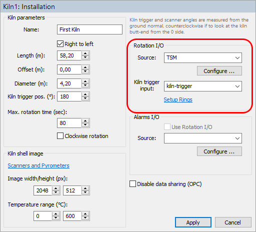
TSM device
If your monitoring system uses TSM device, select TSM as Rotation I/O source. As Kiln trigger input select kiln-trigger.
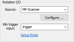
MP scanner as kiln trigger source
You can use the MP scanner trigger input to connect kiln trigger sensor to the system. To do so as Rotation I/O source use MP-Scanner. As Kiln trigger input select trigger.
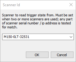
If you have more than one MP scanner in the system, you also need to define which scanner to use. Press Configure button and enter the corresponding scanner ID (a unique part of the scanner ID):
No signal from kiln trigger, Kiln-Trigger alarm
Having stable and reliable kiln trigger signal is very important. There are several abnormal situations related to kiln rotation that the system must handle properly.
If kiln is not rotating or rotating too slowly or if kiln trigger sensor does not function monitoring system will not receive kiln trigger signal in time. Kiln-Trigger alarm is generated If there is no signal from the kiln trigger within the period defined by Max. rotation time parameter.
In case there is no kiln trigger signal, kiln shell image is updated after max. rotation time passes. Such kiln shell images contain more than one revolution if kiln rotation is too slow, or less than one full revolution in case kiln trigger sensor is broken. These images are still valid for zone alarms and envelope alarms conditions, alarm states are updated.
Kiln shell images without correct kiln trigger signal cannot be used to update brick thickness map and are not saved to the history.
Kiln rotation speed is not constant
It is sometimes required during production process to change kiln rotation speed. When speed is changing consequent kiln shell images are slightly distorted in the vertical direction. This has no influence on alarm conditions detection, but does not allow to compare kiln shell images one with another. It is better not to use such images in the brick thickness calculation, so they are not used there and also not saved to the history.
There is no alarm for not constant rotation speed. If rotation is not stable or not measured a warning text is shown on the monitoring window status bar:
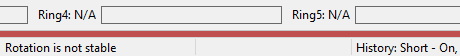
To detect that kiln speed rotation is changing IRT KilnMonitor compares several consecutive revolution times and calculates their variation (maximum - minimum). If measured variation is too big, corresponding kiln shell images are marked as not stable and are not used in brick thickness calculation and are not saved to the history.
Parameters used for rotation stability measurement are taken from Linescano.ini file:
[ROTATION]
stability_samples_count: number of revolutions used to calculate rotation variation;
acceptable_revolution_time_variation: maximum variation value (in seconds) that is considered as stable.
False kiln trigger signals
Contact bounce is easily filtered out by defining a minimum value for time between two consecutive signals.
There is also a filtering mechanism available to detect false signals that come from a not properly working system (with, for example, randomly induced interference). This filtering works like this.
·Average revolution time is constantly maintained by averaging signal periods from last N revolutions.
·When a new signal comes and its period differs from the average by more than X percent, this signal is ignored.
It is possible to adjust signal filtering (and to turn it off) by editing parameters in Linescano.ini file:
[ROTATION]
false_signal_filter_minimum_time: minimum time between two signals in seconds. If next signal comes earlier, it is ignored;
false_signal_filter_size: number of consequtive signal periods used to calculate average rotation time, 0 to turn filtering off;
false_signal_filter_accept_difference: 0..1 (1 corresponds to 100%) - difference to the average rotation period that is still acceptable.