


Setting up the network adapter
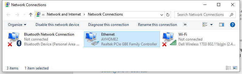
Upon opening the “Network and Sharing Center”, the “Change adapter settings” menu item should be selected. In this menu item, the network card to be used must be highlighted and its properties must be opened using the right mouse button.
Setting the IP address
Before configuring the network card for being used in connection with the camera, the properties of the interface card to be used must be inspected. It is important that fixed IP address is used. The screen-shots shown below provide an overview:
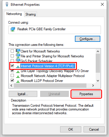
Please note that you only need the components marked above in order to establish an Ethernet connection to the VarioCAM® HD head. Therefore, we recommend deactivating any other components in the list. If the option “Internet protocol Version 4 (TCP/IPv4)” is selected, you can use the “Properties” button to set the IP address of the GigE network adapter.
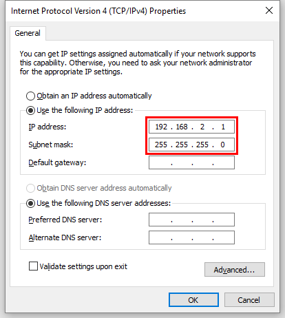
Default camera IP address is 192.168.2.201. Your PC should be in the same subnet, so the IP address of your PC card can be set to, for example, 192.168.2.1.
'Retrieve IP address automatically' option must not be used. If this option is activated, the computer will try to retrieve a dynamic network address from the camera system and no connection will be established.
Configuration of the network card
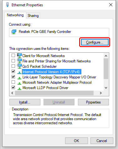
You can use Configure button in the 'Properties of LAN connections' window in order to define the properties of the network card. We strongly recommend activating the Jumbo Packet property in order to achieve a trouble-free Ethernet connection to the VarioCAM® HD head. This function significantly reduces the occupancy rate of the network and allows for loss-free data transmission even at high frame rates. Please note, that if you use a router, it must also support the selected packet size.
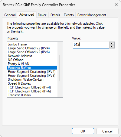
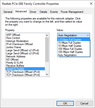
Sometimes it also helps to set Receive Buffers to a higher value and check that Speed & Duplex is at least 1 Gbps Full Duplex.
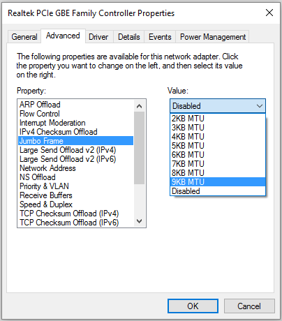
For Jumbo Packet select the highest possible value available in the drop-down list.
For Speed & Duplex preferentially select the value “1.0 Gbps Full Duplex” or “Auto Negotiation” item only if the 1.0 Gbps full duplex value is not available.
For Receive Buffers, selected the maximum accepted value (2048).
Making the connection in IRT Analyzer
Run IRT Analyzer and select 'Camera | Connect' in the main menu. Select 'VarioCam Link' as the driver. Press 'Connect' button.
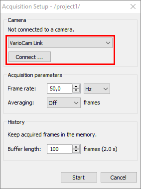
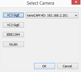
In 'Select Camera' dialog, click on 'VC3 GigE' button and select camera in the combo box (in case you have more than one camera connected):
Using camera triggers
VarioCam HD has two TTL trigger inputs. When trigger is activated, camera sets a flag in the image header. This flag is checked by IRT Analyzer and can be used to start and stop image recording.
This triggering functionality is always off at camera start. To turn it on, a text command must be sent to the camera.
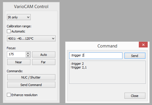
Command “:trigger 2” enables the first trigger input; “:trigger 2,2” enables the second.
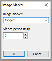
After trigger is enabled in the camera, it can be used in IRT Analyzer, “Img Marker” trigger:
Here is the full description of the :trigger command.
2.217 Command :trigger
Description:
set the camera trigger mode
Invocation:
:trigger <switch>[,<trigger no>]
Parameters
<switch> - the new trigger state
0 = trigger off ( default at camera start )
2 = trigger input ( L/H ) on to generate a high resolution IRB
timestamp
3 = frame sync input on, directly sensor trigger - this trigger type is
exclusive
and do not work for any trigger mode at more than one inputs at the
same time.
5 = trigger input ( L/H ) on to generate a high resolution IRB
timestamp and save a IRB image
8 = frame sync output on
<trigger no> - optional parameter: <switch> effects the I/O line with the number
<trigger no> ( default: 1 )
1 = effects the I/O line 1
2 = effects the I/O line 2
Returns
!trigger <switch>[,<trigger no>]
if successfully, otherwise error message