


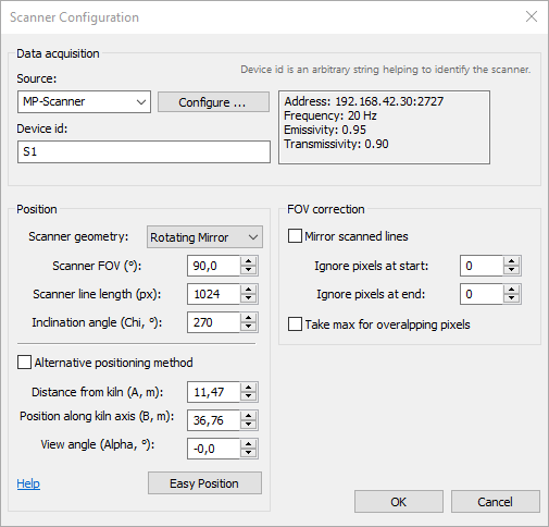
Source: device type used as a scanner (available devices are MP-Scanner, Camera2D). Press Configure button to setup up scanner communication and adjust its parameters.
Device id: used to identify the scanner in messages reporting scanner problems and other cases. Can be any text string you like.
Scanner geometry: possible values are "Rotating Mirror" and "Detector Array". This selection will define the perspective correction formula. It is used when the scanner view angle is not zero.
Scanner FOV: scanner's field of view in degrees.
Scanner line length: number of pixels in the scanned line.
Scanner geometry, FOV and line length are filled automatically after communication with the scanner is established. You can set these values manually in case the scanner is not yet connected to the system. |
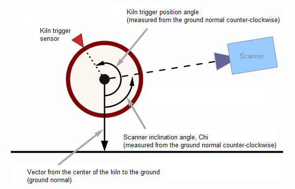
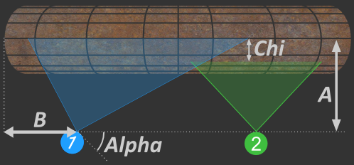
Inclination angle, Chi: angle (in degrees) from the ground normal to the scanner field of view in counter-clockwise direction if to look at the kiln butt end from the kiln axis origin side.
Scanner position
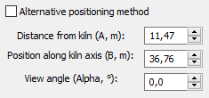
Distance from kiln, A: direct distance from the scanner to the kiln.
Position along kiln axis, B: distance from the kiln origin to the scanner along kiln axis.
View angle, Alpha: scanner view angle, see the picture.
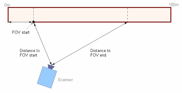
Alternative scanner positioning method
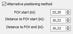
If you mark Alternative positioning method check box, you can use different measures to define the scanner position. In some cases this method is more convenient because you do not need to set scanner view angle which is often difficult to measure.FOV
FOV start: coordinate of the starting point of the kiln area observed by the scanner along kiln axis.
Distance to FOV start: distance from the scanner to to the scanner FOV start point.
Distance to FOV end: distance from the scanner to the scanner FOV end point.
FOV correction
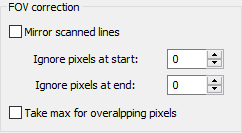
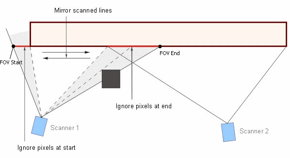
Mirror scanned lines: if marked – before processing, every line coming from the scanner is inverted (mirrored). You may want the scanned lines mirrored if, for example, you have scanners installed on different sides of the kiln. In this case, to have the proper image of the whole kiln on the screen, you need to mirror lines from one of the scanners. Another is of this option is if the scanner is mounted upside down.
Ignore pixels at start: number of pixels to ignore at the beginning of the scanned line.
Ignore pixels at end: number of pixels to ignore at the end of the scanned line.
It may be necessary to ignore some pixels at the start or at the end if, for example, the scanner is installed so that its field of view includes some area that does not belong to the kiln, or if on the path from the scanner to the kiln there is a foreign object that gets into scanner's field of view.
Take max for overlapping pixels: another method to solve problems when two scanners FOVs overlap. If this option is selected, when scanned pixels are rendered to the resulting image, the new pixel replaces the underlying pixel only if its value is higher. See Kiln shell image composition algorithm for more details.
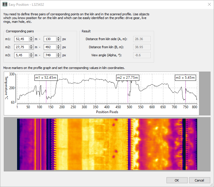
Easy Position
Easy Position function allows to set scanner position without measuring distances and angles. It uses scanned data and recalculates the scanner position by coordinates of know kiln objects visible on the scanned data.
You need to define three pairs of corresponding points on the kiln and in the scanned profile. Use objects which you know position for on the kiln and which can be easily identified on the profile: drive gear, live rings, man hole, etc.
Move markers on the profile graph and set the corresponding values in kiln coordinates.
2D/3D scanners position view
When you change a scanner position or other parameters you immediately see the changes in the kiln view at the right.
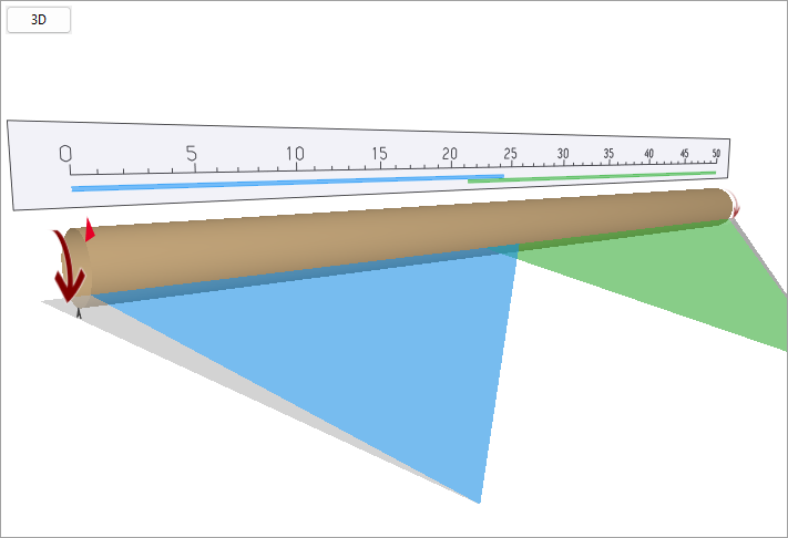
Big burgundy arrow - rotation direction.
Red arrow - position of the kiln trigger sensor on the kiln circumference (position along kiln is not important).
Small gray arrow - zero position on the kiln circumference.
Colorful triangles show scanners' FOVs. Part of a scanner FOV which is not used is shown in gray.
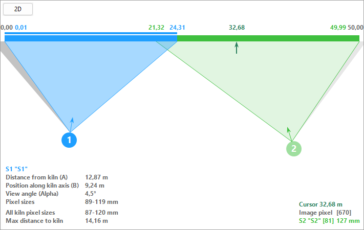
This view shows detailed information about the scanners - their positions and resolution.
Resolution
Resolution is the number of pixels on a scanned line that covers a certain area of the kiln.
The pixel size is the reciprocal of the resolution and indicates the area of the kiln shell that corresponds to one pixel on the scanned line.
Pixel size is important because if the size of a hotspot we want to measure temperature of is smaller than the pixel size, we won't get correct temperature value - it will be averaged with the temperature of a spot lying next to our hotspot. In fact, the pixel size should be half the size of the hotspot whose temperature we are measuring. For kiln monitoring the smallest hotspot size we are interested in is usually the refractory brick size.
This view shows pixel sizes only along the X coordinate.
Areas on the kiln shell that are further away from a scanner have worse resolution on the scanned kiln infrared image than areas that are closer to the scanner. IRT KilnMonitor automatically corrects these resolution differences when the kiln shell image is displayed on the screen using approximation for areas with lower resolution.
What we see in the 2D kiln view
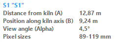
Here we see information about the selected scanner - its position and the best and the worst resolution.
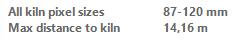
Here we see the best and the worst resolution along the entire length of the kiln, as well as the straight distance to the furthest scanner.
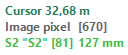
Here we see information about the kiln position indicated by the cursor. The cursor is an arrow next to the kiln strip, it can be moved with the mouse.
[670] - pixel number on the kiln image.
[81] 127 mm - pixel number on the scanner line and the size of this pixel in kiln coordinates.
Positioning scanners using the mouse
Scanner edit mode must be active to move the scanners with the mouse. Scanners are in edit mode when the scanners list edit dialog or the single scanner edit dialog box is open.
·Double-click the scanner circle to activate it and open its editing dialog box. If you double-click outside any scanner, the scanner list edit dialog will show up and you will be able to reposition any scanner, not just the active one.
·To change the position of a scanner, press the left mouse button on the scanner circle and, while holding the button, move the mouse.
·Use the mouse wheel to change scanner view angle.
·Hold the Shift key on the keyboard while moving the mouse to change the position of the scanner without changing the scanned part of the kiln (Fixed FOV Move Mode).