


Installation page is protected by Level 2 password.
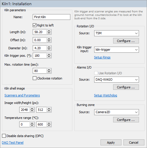
Kiln Parameters
Name: the name of the kiln to be displayed in the monitoring screens. You can use any name you like.
Length: the length of the kiln (or part of the kiln exposed to the IR scanners).
Right to left: if the check box is not marked – kiln axis direction goes from left to right, if marked – kiln axis goes from right to left.
Offset: the kiln position offset. Allows kiln position to begin with value other than 0. Changing this value will change refractory positions accordingly.
Diameter: the diameter of the kiln.
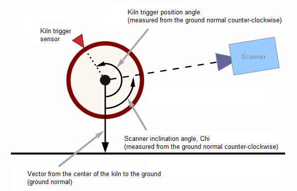
Kiln trigger position: the angle (in degrees) to the kiln trigger sensor. The angle is measured from the ground normal vector, in the counter-clockwise direction if to look at the kiln butt-end from the kiln axis origin side. See the picture below.
Maximum rotation time: the maximum time of one full kiln rotation in seconds. If kiln trigger signal is not coming during this period of time, Kiln-Trigger alarm is generated.
Clockwise rotation: check box marked means that the kiln rotates clockwise, otherwise – counter-clockwise (if to look at the kiln butt-end from the kiln origin side).
Disable data sharing (OPC): if marked, disables remote access to this kiln. It will be not possible to view this kiln using IRT KilnMonitor clients. Also measured data will not be published through OPC.
Kiln infrared image
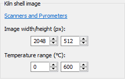
Temperature data from all scanners and pyrometers is rendered into one kiln shell image. This section defines the parameters of this image.
Image width/height: you can select any width and height values, IRT KilnMonitor will automatically interpolate lacking data or remove redundant data. Please follow these recommendations to get a higher quality kiln image and a better looking monitoring screen:
1.The image width should be close to the number of pixel the scanner line has. If more than one scanner is used in monitoring - the sum for all scanners should be taken.
2.The image height should be selected taking into consideration the size of the smallest spot the monitoring system needs to detect. Height in pixels = kiln circumference / spot size. For example, if kiln is 3 meters in diameter and we want to have 5 cm resolution, image height = Pi * 3 / 0.05 = 188 pixels. So image height should be 188 pixels or more.
3.If to take into account the way kiln shell image is displayed on screen in IRT KilnMonitor and consider additional windows and analysis, it is better if the image height will be in the range of 1/3 to 1/4 of the image width.
See Kiln shell image composition algorithm for kiln shell image rendering details.
Temperature range: possible minimum and maximum kiln shell temperature. The monitoring system will not be able to display temperatures outside this range.
Scanners and pyrometers
Click Scanner and Pyrometers link to display the list of scanners and pyrometers:
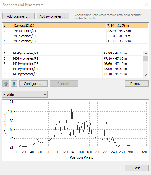
To add a scanner to the system press Add scanner button.
To add a pyrometer press Add pyrometer button.
To change selected scanner or pyrometer configuration double click on the scanner or pyrometer name in the list or press Configure button.
To test a scanner or a pyrometer communication and see its data select the scanner or pyrometer in the list and press Connect button. Device data will be displayed in the window below the list.
See Setting up a scanner and Setting up a pyrometer for each device configuration details.
Scanner and pyrometers list order
The order of scanners and pyrometers in the list is important because it affects the order temperature data is rendered to the resulting kiln shell image in the areas where scanners' and pyrometers' FOVs overlap. See Kiln shell image composition algorithm for more details.
Rotation I/O
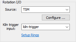
This section defines hardware used to register kiln revolutions and to measure tire slip values for kiln external rings.
Source: the device type used for signals input (can be TSM, MP-Scanner, DAQ-WAGO and signal simulation timers). Press Configure button to configure connection and other parameters of the selected device.
Kiln trigger input: the name of the input used to receive signals from the kiln trigger sensor (different device types use different input names).
Setup Rings: click the link to define kiln external rings and select inputs used by their revolution sensors.
See Kiln trigger and Tire slip monitoring for details.
Alarms I/O
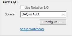
This section defines hardware used to trigger external alarms.
Source: device type used for signals output. Press Configure button to configure connection and other parameters of the selected device.
Use Rotation I/O: mark this check box to use the same device for both signal inputs and outputs. Enabled only if selected Rotation I/O device in addition to inputs has also outputs.
Setup Watchdog: click the link to define parameters of the watchdog. This link is available only if selected I/O device supports watchdog functionality.
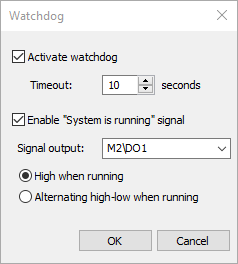
"System is running" signal
"System is running" signal is not available if the selected alarm I/O device does not support watchdog.
This signal can be used to ensure that kiln monitoring system is running and there are no problems with the monitoring hardware and software:
1.PC is running, IRT KilnMonitor is running, kiln monitoring is started.
2.Devices used for monitoring kiln temperatures are functioning properly: the scanners and pyrometers send data, the kiln trigger signal comes in expected intervals.
Note "System is running" state is not affected by problems with the ring revolution sensors even if the problems are hardware related. "System is running" state is not affected by the alarm states (zone alarms, maintenance alarms and others). |
Burning zone
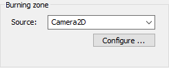
This section defines the device used to monitor the burning zone temperature. This can be an infrared camera (TV40) or an pyrometer (Endurance).
See Burning zone monitoring for details.