


Modbus is a serial communications protocol originally published by Modicon in 1979 for use with its programmable logic controllers (PLCs). Modbus has become a de facto standard communication protocol and is now a commonly available means of connecting industrial electronic devices. The main reasons for the use of Modbus in the industrial environment are:
·developed with industrial applications in mind,
·openly published and royalty-free,
·easy to deploy and maintain,
·moves raw bits or words without placing many restrictions on vendors.
Modbus TCP/IP or Modbus TCP is a Modbus variant used for communications over TCP/IP networks, connecting over port 502.
Notes 1.When configured, IRT Analyzer behaves as a Modbus slave or server device. It does not establish communication with other devices by itself, but only reacts to transmissions originated by other modules (called Modbus masters or clients). A client device is needed to receive and interpret data produced by IRT Analyzer. 2.IRT Analyzer Modbus TCP server starts when DAQ Configuration dialog is opened or when the automation mode is started or being configured. Otherwise, the server is not running and is not visible for other devices in the network. Once the server is started it continues to run as long as IRT Analyzer is running. |
Configuring Modbus TCP server
Modbus TCP server in IRT Analyzer is implemented as a DAQ module and can be enabled in 'DAQ Configuration' dialog (main menu 'Automation | DAQ Configuration').
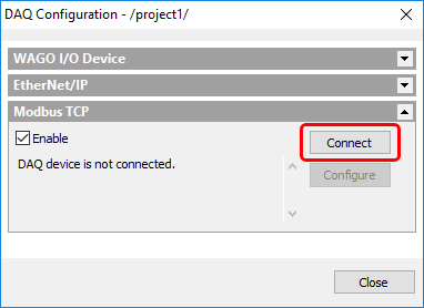
Firstly, it is necessary to specify which Ethernet adapter (PC may have several Ethernet adapters) is to be used by the Modbus server. Press 'Connect' button to select an adapter. When Ethernet adapter is selected you will see a message confirming this: "Connected to 192.168.1.33 - Local Area Connection".
After that you need to define how many inputs and outputs are needed to cover all inputs and outputs used in your automation project. Press 'Configure' button.
Note Please note that from the network point of view (Modbus client side) data directions reverse. IRT Analyzer input data is output data for clients/network and IRT Analyzer output data is input data for clients/network. |
PC (IRT Analyzer) side
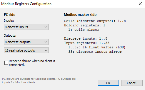
On the PC side we define how many inputs and outputs are needed. These numbers depend on your automation project needs.
·Discrete inputs: we can use each input as an input for DAQ conditions.
·Discrete outputs: can be used as alarm and signal outputs.
·Real value outputs: 4-byte floating point numbers used as outputs for measurements.
Modbus master (network) side
Up to 16 clients can connect to IRT Analyzer Modbus TCP server simultaneously.
The following table describes object types provided by IRT Analyzer Modbus slave to a Modbus master device:
Object type |
Access |
Size |
Usage |
|---|---|---|---|
Discrete inputs |
Read-only |
1 bit per input |
IRT Analyzer discrete outputs go here. |
Coils |
Read-write |
1 bit per coil |
IRT Analyzer uses coil states as discrete inputs. |
Input Registers |
Read-only |
16 bits per register |
IRT Analyzer measurement outputs are stored in these registers. Each value (4-byte floating point) occupies 2 registers in LSB order. |
Holding Registers |
Read-write |
16 bits per register |
IRT Analyzer uses these registers only for coils mirror (see below). |
Object addresses start from 1.
Discrete inputs and coils mirror
One or more registers are used as mirror for discrete inputs and coils. This allows to read full state (both registers and discrete inputs) with one Modbus read command (can be useful because of performance reasons). Mirror registers go right after the "normal" registers.
'Report a failure when no client is connected' option
When IRT Analyzer depends on external signals, it is important to properly handle situations when there is nobody connected and data is not sent (Modbus master is not connected).
Event |
Option is enabled |
Option is disabled |
Master device is not connected when automation mode starts. |
All processing is suspended until Master device is connected; a wait dialog is shown. |
Automation mode starts immediately, input values are undefined. |
Master device disconnects when automation is running. |
The system goes to the failure state, input values are undefined. |
No system failure, input values keep their last set states. |