


Protected by Level 1 password.
Alarm conditions can be defined for different kiln parts. When an alarm condition is met alarm is displayed on the monitoring screen and also can be reported to an external expert system with the help of external outputs (Alarms I/O).
To configure alarm conditions select Alarms item in the tree structure at the left part of the Configuration window. Before you can define alarms, Installation part of the configuration must be ready and working, you should have access to the scanned data and to the alarms I/O device. See topic Kiln dimensions and monitoring hardware for details.
Envelope profile alarms
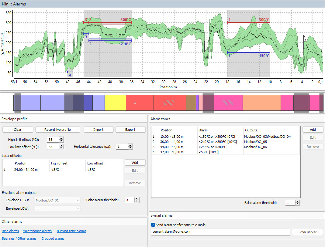
Kiln envelope profile can be used to define permissible temperature range for every position along the kiln. The main idea behind it is to record kiln shell temperatures when the kiln is in a good condition, and then check that the temperature at each position does not differ too much from the original good value. When the difference is too big, Envelope alarm is generated.
There are several ways to define the envelope profile:
1.Record current kiln temperatures: press Record live profile button, the live profile will start forming the envelope profile. Press the same button again (then it is called Stop live profile) to stop forming the envelope profile.
2.Import from a previously stored infrared image of the kiln shell: press Import button and select a path to a previously stored infrared image of the same kiln.
3.Import from a text file: press Import button. In the File Open dialog, in the Files of type combo-box, select Envelope files (*.txt) and locate a text file with envelope values.
To define how much temperatures of the kiln are allowed to differ from the recorded envelope use High limit offset and Low limit offset fields. Two gray lines on the envelope graph shows the initial envelope - the envelope without offsets.
To prevent false alarms caused by possible horizontal displacement of the kiln, use the Horizontal tolerance parameter, which is defined in pixels.
You can also add offsets to the envelope locally. Use Local offsets list for that.
Envelope alarm outputs: when measured kiln temperature at some point goes outside the limits defined by the envelope profile, an alarm is generated. Envelope HIGH is generated when the upper limit is passed, Envelope LOW - the lower limit. You can select external outputs that will be triggered when the alarm is active.
False alarm threshold: indicates for how many kiln revolutions the alarm condition should be met to trigger an alarm.
You can define a temperature limit that should not be exceeded at some particular part of the kiln. You can define both upper and lower limits.
When the limit is exceeded, an alarm signal is triggered. This signal can be forwarded to an external output. The alarm message will also appear on the computer screen.
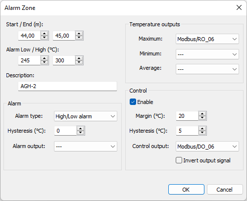
To add an alarm zone press the Add button in the Alarm zones frame. An alarm zone is defined by the following parameters:
·Start / End: start and end positions along the kiln axis.
·Alarm Low / High: lower and upper limits to trigger an alarm.
·Alarm type: can be "High/Low alarm", "High alarm", "Low alarm" or "Off".
·Hysteresis: hysteresis to prevent alarm from turning off too quickly. For example, in the event of a high alarm, the alarm is activated if the measured temperature rises above the high limit. The alarm is deactivated only after the temperature has dropped below the limit minus the hysteresis value.
·Alarm output: name of the external output for the alarm signal. It can also be the beeper or no output.
·Temperature outputs: alarm zone maximum, minimum and average values can drive analog outputs.
Alarm zones are marked on the diagram with red and blue horizontal lines and zone numbers.
Alarm zone Control
Alarm zone control defines an additional condition which is triggered earlier than the alarm condition. The control condition is set by the Margin property. The margin value is subtracted from the alarm level, it defines the level when the control condition is turned on:
For “High alarm” zones the control condition is on when the temperature of the zone is higher than the alarm level minus the margin.
For “Low alarm” zones the control condition is on when the temperature is lower than the alarm level plus the margin.
For “High/Low alarm” zones the control condition is on when the temperature is higher than the alarm level minus the margin or lower than the alarm level plus the margin.
The control condition also has its own Hysteresis setting, it prevents the control output from turning off prematurely.
Control output – hardware output used to turn on/off external hardware.
Invert output – sets the output to zero when the control condition is met and to one when it is not.
The actual control state is displayed in the alarm list of the monitoring window and also on the horizontal profile.
Note If you specify a new zone which overlaps previously defined zones, the existing zones will be sized or deleted to free space for the new zone. To define an alarm zone that corresponds to a brick zone, double-click on the brick zone in the refractory view below the kiln profile. |
Analog output range: for 4..20 mA analog outputs defines which temperature value corresponds to 4 mA and temperature value that corresponds to 20 mA. Similar for VDC analog modules. For digital interfaces like Modbus these values can be configured but are not used.
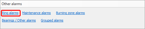
Ring alarms
Ring alarm is an alarm that informs that something is wrong with a kiln external ring. Ring alarm is generated when measured tire slip value for a ring goes out of the defined limits or a problem with the revolution sensor is detected and there are no changes registered in the kiln rotation speed that could influence tire slip measurement.
Rings and corresponding revolution sensors are defined on the Installation page. Here you define permissible tire slip limits, tire slip calculation parameters and hardware outputs.
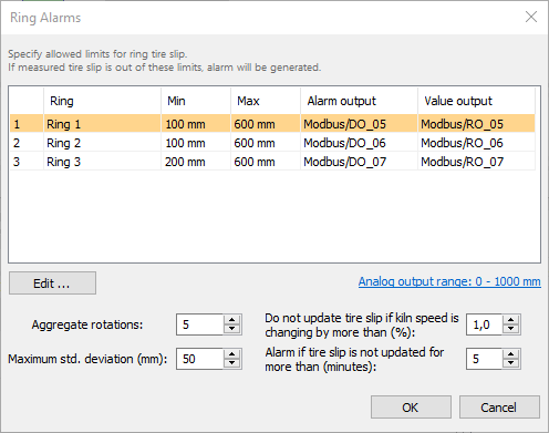
To learn what Aggregate rotations, Maximum std. deviation and other parameters mean please see Tire slip monitoring topic.
Double click on a ring to change alarm settings for this ring:
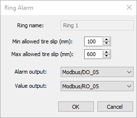
Minimum allowed tire slip: if measured tire slip value is smaller than this value alarm is generated.
Maximum allowed tire slip: if measured tire slip value is larger than this value alarm is generated.
Alarm output: discrete output that is set to 1 when alarm related to this ring is detected.
Value output: analog output which value is changed according to the measured tire slip value.
Analog output range: defines what temperature value corresponds to the lowest output signal value and what temperature to the highest.
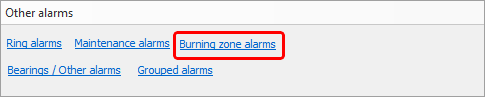
Burning zone alarms
You can control the temperature of the burning zone and be sure that it stays withing the required range.
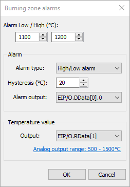
·Alarm Low / High: lower and upper limits to trigger an alarm.
·Alarm type: can be "High/Low alarm", "High alarm", "Low alarm" or "Off".
·Hysteresis: hysteresis to prevent alarm from turning off too quickly. For example, in the event of a high alarm, the alarm is activated if the measured temperature rises above the high limit. The alarm is deactivated only after the temperature has dropped below the limit minus the hysteresis value.
·Alarm output: name of the external output for the alarm signal. It can also be the beeper or no output.
·Temperature value output: analog output to be set by the measured burning zone temperature.
·Analog output range: the range used to convert the temperature value to the output level (current or voltage).
Bearings / Other alarms
To setup temperature limits for bearings (other monitored objects) use Bearings / Other alarms dialog. Each monitored object has its own alarm settings.
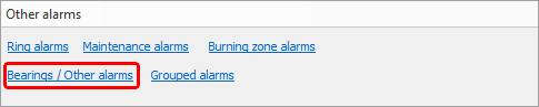
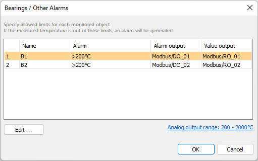
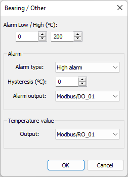
Alarm parameters are the same as for the Burning zone alarms.
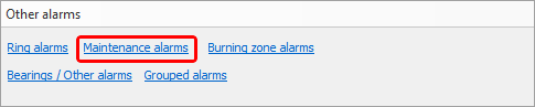
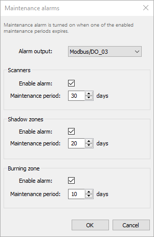
Maintenance alarms
Purpose of a maintenance alarm is to remind that it is time to inspect the hardware - check that everything is fine, clean the lenses and so on.
There are three groups: scanners, shadows zones (pyrometers) and burning zone. Each group has its own period.
Grouped alarms
Alarms that are aggregation of other alarms.
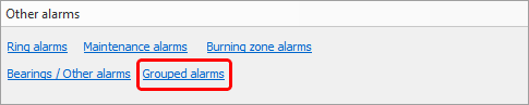
There are three such aggregations/groups: All kiln alarms, All system alarms, and Scanner alarms.
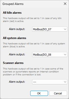
All kiln alarms
This group includes all kiln state alarms (alarms shown in red in the monitoring window): envelope alarms, alarm zones, ring alarms, bearing alarms, burning zone alarms. Selected hardware output will be set to 1 in case any kiln state alarm is active.
All system alarms
This group includes all system alarms (alarms shown in blue in the monitoring window): kiln trigger alarm, scanners alarm, maintenance alarm, refractory alarm. Selected hardware output will be set to 1 in case any system alarm is active.
Scanner alarms
Scanner alarm is triggered when there is a problem with a scanner or with a pyrometer.
Causes for the alarm are:
·Connection lost, data from a scanner or pyrometer stops coming.
·Scanner or pyrometer internal temperature is higher than the defined limit.
·Scanner or pyrometer reported an error state.
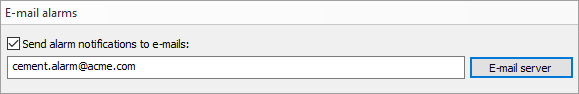
E-mail alarms
It is possible to configure IRT KilnMonitor to send notification e-mails in case of alarms. The e-mail is sent when active alarm list is changing.
E-mail server
In order to send e-mails, IRT KilnMonitor needs access to an e-mail server that will handle e-mail delivery. To configure server settings press E-mail server button.
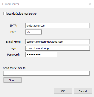
SMTP: address of the e-mail server.
Port: port to use to send e-mail messages to the server.
E-mail From: source e-mail address (alarm notifications will be coming from this address).
Login: login required to sign in to the e-mail server.
Password: password required to sign in to the e-mail server.
Testing that e-mail server is configured properly
To test that e-mail server configuration is correct, try to send a test e-mail to any address of yours. Type the address in the Send test e-mail to field and press Send button.
Alarm outputs
Sound alarm outputs
These sound outputs are always available:
·Beeper: sound signal from the beeper;
·Sound/Alarm: alarm siren (with 3 seconds turn-off period);
·Sound/AlarmQF: alarm siren (with short turn-off period).
Outputs sharing
I/O hardware outputs and sound alarm outputs can be shared by several signal sources (alarms):
·Signal sources that can share same outputs: alarm zones, envelope profile alarms, ring alarms, maintenance alarms, scanner alarms, burning zone alarms, grouped alarms.
·Signal sources that use outputs exclusively: alarm zone controls, ‘system is running’ signal, all value outputs (temperature, tire slip).
·Outputs can be shared only within one kiln. Two kilns cannot use the same output (but sound alarm outputs still can be used).